
A Potentiometer sensor measures position by converting motion into a proportional electrical signal. When a machine needs a simple way to confirm travel, angle, or knob position, this sensor is often the first option engineers consider because it is easy to integrate, easy to scale, and easy to verify during startup. If you want a quick internal refresher on selection and specification basics, link to What is Potentiometer Sensor? within your knowledge base.
In industrial controls, performance comes down to signal stability under real conditions, not just the datasheet value. That is where Sensors in Potentiometer decisions matter, including how the element is built, how the wiper contact behaves over time, and how mounting and wiring protect the signal from vibration and electrical noise. A good selection approach connects the sensor type to the mechanism, then confirms it with a short acceptance check you can repeat later.
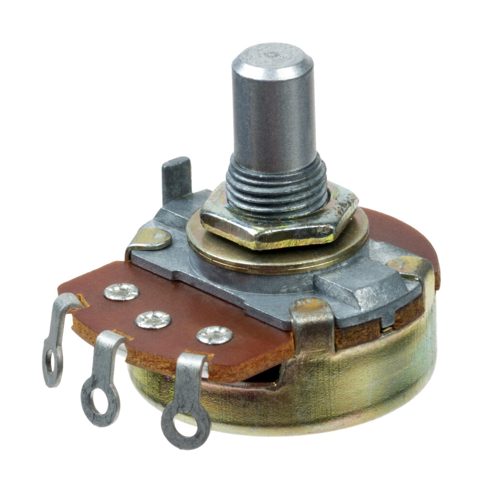
A Potentiometer sensor is a resistive position device. As the shaft turns or the slider moves, the wiper travels along a resistive track and changes the resistance ratio between the end terminals and the wiper output. When you apply a stable reference voltage across the end terminals, the wiper output becomes a proportional voltage that represents position.
From a controls perspective, the goal is simple. The controller needs a signal that moves smoothly with motion, stays repeatable from cycle to cycle, and uses enough of the input range to show small changes without amplifying noise. Many issues that look like controller problems are really mechanical alignment, worn contact zones, or wiring practices that allow noise into the input.
When teams say “Sensors in Potentiometer,” they are usually talking about the sensing element and contact system that create the output signal. Track material, contact force, and mechanical construction influence how the sensor behaves under duty, temperature changes, and vibration. These details affect noise, repeatability, and life more than resistance value alone.
For most industrial builds, the practical question is whether the sensor will hold a stable output in the working band. If the mechanism moves in a narrow range, you want the best resolution and lowest noise in that band. If the equipment runs continuously, you want a construction that fits the duty profile and does not develop noisy zones quickly. This is also where internal documentation helps, so teams often reference Potentiometer within their internal library to keep selection decisions consistent.
A Potentiometer sensor is used anywhere a system needs continuous position feedback without adding complexity. It shows up in operator controls, mechanical linkages, valve travel feedback, actuator stroke measurement, and equipment calibration points. The common thread is that the mechanism has a physical motion, and the controller needs a stable, readable value.
The best applications are the ones where the sensor can be mounted securely, aligned to the motion, and protected from side loading. When those conditions are met, the signal is predictable, scaling is straightforward, and maintenance can verify performance quickly using a saved baseline.
When an actuator extends or a slide moves, the controller often needs to confirm where it is in travel, not just whether it reached an end stop. A Potentiometer sensor provides a continuous position value that supports smooth motion control, tighter limits, and faster fault isolation when something binds or drifts.
In these use cases, Sensors in Potentiometer choices often come down to stroke alignment and mounting stability. If the electrical stroke matches the usable mechanical travel, the controller sees clear resolution in the working band. During commissioning, a baseline sweep and a few repeatable position checks give you a reference for later service.
On many machines, an operator knob or lever still needs a reliable analog position signal. A Potentiometer sensor works well here because it is intuitive, quick to scale, and easy to validate during setup. The controller reads a stable value, the HMI can display a meaningful percent, and the operator gets a predictable response.
For these controls, the reliability of Sensors in Potentiometer depends on feel, repeatability, and noise behavior near the setpoint range that operators use most. A simple acceptance pass, such as checking smooth output through the working range and confirming endpoints, helps avoid small issues that later show up as jumpy control.
Valves and linkages often move through a defined range where small position changes matter. A Potentiometer sensor can provide continuous travel feedback that helps the controller confirm commanded movement and detect drift or sticking over time.
Here, the Sensors in Potentiometer performance are strongly influenced by mechanical loading. Side loading and misalignment can create wear and noisy zones even when the electrical design is fine. Stable mounting, clean linkage geometry, and protected wiring usually deliver the biggest reliability gains.
Selection starts with the motion and the working band. Define the usable travel or rotation, then map that range to the electrical span so the controller uses a strong portion of its input range. This improves resolution and keeps small moves visible without chasing noise.
Next, treat Sensors in Potentiometer selection as a system decision. Consider vibration, temperature, moisture, and duty cycle, then choose a mounting approach that keeps alignment stable over time. If your team needs a consistent selection process, the internal reference Potentiometer helps keep part choices and verification steps aligned across projects.
Mechanical alignment is the foundation of signal stability. Keep the sensor in line with the mechanism so it is not side-loaded, and avoid coupling methods that introduce play that will show up as jitter. Route signal wiring away from high-current lines, use appropriate shielding when needed, and keep grounding consistent so the controller sees real motion, not electrical interference.
For commissioning, keep the checks short and repeatable. Confirm endpoints, verify scaling at a few known positions, and record a baseline sweep or step check in the working band. Save the results with the part number and install notes. Later, when a technician replaces a part or a bracket shifts, the team can compare today’s readings to that baseline and isolate the root cause faster.
Most long-term issues are not surprises. Wear shows up first as increased noise or reduced repeatability in a high-use zone, and wiring issues show up as intermittent jumps that correlate with load changes. A simple trend check during planned maintenance can catch these early, especially when you have baseline readings to compare.
When you document the final scaling values and quick acceptance checks for sensors in potentiometer, field replacements stay consistent, and verification stays fast.
A Potentiometer sensor is used to measure position, travel, or angle and provide a proportional signal that the controller can use for feedback, limits, or operator input.
Accuracy depends on the device construction, the working band, and the installation. With stable mounting and correct scaling, a Potentiometer sensor can deliver repeatable position feedback suitable for many industrial control tasks.
Common causes include side loading, worn contact zones, poor grounding, and routing signal wiring next to high-current power. Managing sensors in the potentiometer installation details usually improves stability more than changing controller settings.
Apply a stable reference across the end terminals, then map the wiper output to the controller input range using known endpoints and a few mid-range checks. Save the values as a baseline so future service can confirm the signal quickly.
Verify alignment, confirm endpoints, and record a baseline sweep or a few repeatable position checks in the working band. These checks make it easier to compare future performance and troubleshoot changes.