A Potentiometer helps a control system understand position without adding complexity to the machine. When the signal is stable, tuning is faster, limits behave predictably, and troubleshooting stays grounded in measured data instead of guesswork. The selection for the right Potentiometer for your application should start with the type of motion you are measuring and the real working range you will use, because that single decision shapes mounting, scaling, and long-term repeatability.
The best results also come from treating the setup like part of the design, not an afterthought. A strong Potentiometer Application includes a simple commissioning baseline so future service checks can compare today’s readings to known good behavior. When the device, the mechanics, and the wiring are aligned early, the feedback stays consistent through seasonal changes, rebuilds, and routine maintenance.
The job of a potentiometer in industrial control is simple in concept and demanding in practice. It converts mechanical movement into a proportional electrical value that the controller can scale into position. That position value is used for everyday decisions such as confirming end points, holding a setpoint, detecting drift, and verifying that a mechanism returned to home.
The selection should also account for how the signal will be read. A controller input that is scaled correctly will see small moves without amplifying noise, while poor scaling can make the same hardware feel unstable. If you want a deeper, step-by-step overview of specification basics, read Potentiometer to learn more.
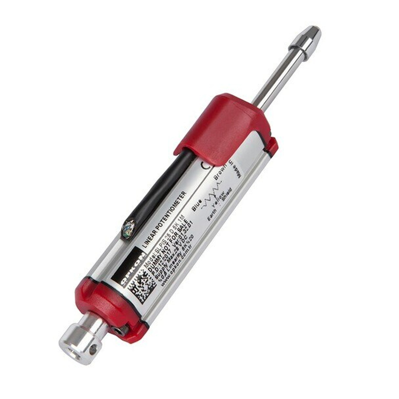
The selection for a Linear Potentiometer should start with straight travel, where you need continuous feedback, not just a limit switch. You will commonly see this approach on cylinders, slides, guided actuators, and linkages, where the system benefits from knowing where the mechanism is throughout the stroke. When alignment is stable and side load is controlled, the signal becomes a reliable map of travel that supports tighter limits and smoother motion behavior.
A good installation focuses on stroke matching and repeatability. Map the usable mechanical travel to the usable electrical stroke with a small margin so normal motion never rides the endpoints, then confirm a few repeatable positions during commissioning and save the readings with the part number. If you want a practical guide to sizing, mounting, and verification steps, read Linear Potentiometer to learn more.
The selection for a Single-Turn Potentiometer should start with rotary mechanisms that move within a defined angle and return to the same stops each cycle. Common examples include selectors, handles, dampers, and rotary linkages, where you want a clean proportional signal across a limited window. Because the full electrical span is covered within one turn, scaling is usually straightforward, and small changes in angle show up clearly at the input.
A practical startup check keeps performance predictable. Confirm the mechanical stops, verify output at a few known angles, and look for a smooth change without noisy zones, then record those values as your baseline. If you want more details on mounting and quick verification checks, read Single-Turn Potentiometer to learn more.
The selection for a Multi-Turn Potentiometer should start with applications that need finer adjustment across multiple turns, such as calibration tasks, extended rotation mechanisms, and positioning setups that require more usable resolution per degree. Spreading the resistance change across several turns makes the output feel more controlled, especially when small knob changes need to produce small, repeatable signal changes.
Because multi-turn designs often rely on internal gearing, handling and mounting discipline matters. Verify smooth output across the full adjustment range, then record repeatability from both approach directions so later checks are quick and consistent. If you want a deeper guide for setup and verification across turns, read Mutli-Turn Potentiometer to learn more.
The selection for the right device should start with motion, range, and how the machine will actually use the signal. Straight travel points to linear feedback, limited rotation points to single-turn behavior, and extended rotation with fine adjustment points to multi-turn behavior. From there, confirm the environment and duty cycle so temperature, vibration, and cycle count do not push the device into unstable behavior over time.
A reliable Potentiometer Application also depends on service reality. Choose mounting that can be replaced without re-machining brackets, protect the harness so movement does not fatigue conductors, and keep signal routing away from high current runs so the controller sees the position instead of interference. When you also save a short baseline at commissioning, troubleshooting becomes a clean comparison rather than a debate.
The selection for a stable feedback system should always include alignment and wiring practices, because most problems come from those two areas rather than the datasheet. Keep the mechanism aligned so the sensor is not side-loaded, and avoid couplers or linkages that introduce play that later appears as jitter. Route signal wiring with separation from power, keep grounding consistent, and verify readings while the machine is running, not only on a bench.
Commissioning is where you lock in confidence. Record scaled endpoints, confirm smooth response through the working band, and save a simple baseline check that maintenance can repeat later. That approach supports a Potentiometer Application that stays predictable even after a swap, because today’s values can be compared to the original acceptance record.
The selection for real machines is easier when you think in use cases instead of catalog categories. A Linear Potentiometer is often the right choice when a controller needs continuous feedback across a stroke, and the linkage can be kept aligned. A Single-Turn Potentiometer is often the right choice when rotation is limited, and you want a clean, proportional command or feedback signal that scales quickly.
A Multi-Turn Potentiometer is often the right choice when fine adjustment across multiple turns matters more than fast rotation, such as calibration and positioning setups. In each case, reliability improves when the signal is scaled to use a strong portion of the controller input range and when a short baseline is saved at startup so future checks stay consistent.
A Potentiometer is used to convert movement into a proportional signal that the controller can scale into position for feedback, limits, and adjustment.
A Linear Potentiometer is a strong fit for straight travel feedback on slides, cylinders, and linkages where continuous position tracking improves control.
A Single-Turn Potentiometer fits mechanisms with a defined angle window where scaling and endpoint checks need to be quick and repeatable.
A Multi-Turn Potentiometer supports finer adjustment across multiple turns, which helps calibration and positioning setups stay repeatable.
Record scaled endpoints and a short baseline in the working band so a future Potentiometer Application check can compare readings to known good values.