Mobile equipment needs inputs that hold scale in rough work. Hall-Effect Joysticks read a magnet’s field with a Hall IC, turning lever motion into a clean, ratiometric signal. Tie the sensor to the ECU reference, plan counts per degree, and set a center band that feels steady with gloves. Check smooth, monotonic output across the throw at crawl speed.
Choose a magnetic layout that stays linear through shock. Size outputs for the ECU input and add dual channels for plausibility checks. Log a baseline sweep, a five percent step to sixty-three percent, and the final error. These records speed service and keep fleets consistent.
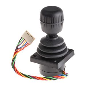
To set up the joysticks effectively, start by calibrating them with precision. Align the lever’s angle with the controller’s range, define your center points, and establish clear limits. Opt for a robust magnetic design and strong wiring to enhance durability in challenging environments. A narrow center band will improve stability, while regular performance checks will keep everything running smoothly and reliably over time. For panel dials used alongside joysticks, read Rotary Potentiometer Working Principle.
Magnetic Layouts for Mobile Duty: Magnets, Air Gap, Tolerance
When designing a magnetic sensor, the geometry of the magnets plays a crucial role in determining both the resolution and the overall feel at the center. Using axial magnets combined with a flux guide tends to provide a smooth response during mid-travel. On the other hand, diametral ring magnets can create stronger responses at the edges.
It’s important to keep a steady air gap while moving to ensure the magnetic field works well. Also, think about the mechanical tolerances in your budget. This will help the integrated circuit (IC) stay in the right place, even if it faces shocks or changes in temperature.
For the bracket and lever design, ensure they help maintain proper alignment. A solid mount for the Hall IC is essential, along with a keyed pocket for the magnet that prevents it from rotating. Make sure to test the output in both directions gradually, and take note of the knee points at the ends of the travel for your acceptance file. For extended-angle devices that complement mobile controls, see How Does a Multi-Turn Potentiometer Work.
Mobile Power and EMC: 12/24 V Systems, Surges, Harness Layout
When working with mobile electronic control units (ECUs), it’s important to manage electrical spikes and load dumps. Start by powering joysticks from a safe, fused source. Regulate the power close to the components. Keep the signals consistent with the references for your analog-to-digital converter (ADC).
To protect your equipment from electrical pulses, use transient voltage suppressors (TVS). Adding some resistance in series can help, too. Make sure to bond the device’s body at one point. Also, keep twisted wires away from motors and pumps to reduce interference.
Choosing the appropriate wiring harness is essential for reliability. Utilize sealed connectors such as AMPseal or Deutsch. Add a drip loop to allow for drainage and some flexible support to prevent strain on the wires. Ground the shields at one end only.
During setup, introduce a small disturbance to check that the readings remain steady. This ensures everything is working properly. For valve loops, these joysticks often command, see ETI System: Control Valve Actuators and Positioners.
Output Strategy and Diagnostics: ECU Scaling, PWM, Redundancy
When connecting outputs to the ECU, it’s important to pick the right type. For short harness runs, use ratiometric 0–5 V signals tied to the reference. If the input expects a duty cycle, go for PWM signals instead. Make sure to scale the travel so that a 0 to 100 percent command fits within the ECU’s range without causing clipping.
Store the center, endpoints, and a checksum. This way, the software can easily verify a valid set of values. For added safety, use dual channels. Wire channels A and B with different spans and have the ECU compare their outputs. If there’s a mismatch, trigger a quick safety mode.
Also, keep track of latency up to sixty-three percent and any final errors during a 5 percent step change. Record these numbers along with the serial number and ambient conditions to help with quick checks in the field. For a deeper primer on sensing and scaling, read How do Hall Effect Joysticks Work?.
Ergonomics for Gloves and Vibration: Throw, Force Curve, Detents
When designing gloves, aim for a calm and steady center. Adjust the spring so the lever settles smoothly without any issues and provides more effort towards the ends. Incorporate light detents to signal important functions without making the stick jolt. Make sure the throw allows for fine adjustments while keeping full travel easy from the seat.
Consider comfort for long shifts and create moves that are easy to repeat. Angle the grip to fit the operator’s hand and ensure there’s a clear index for guidance. Choose a knob size that allows for a secure grip, even when wearing gloves. Regularly check for center drift and hysteresis by performing slow passes, and remember to keep a record of the curve for maintenance purposes.
Enclosures and Seals: IP Ratings, Breathable Barriers, Materials
Cabins are exposed to dust, spray, and temperature changes. It’s important to choose the right IP level for your cleaning routine. Use components like shaft seals, boots, and rated glands. Adding a hydrophobic breather can help manage condensation effectively. You should verify this setup with a quick spray test and check the angles afterward.
When selecting materials for the site, opt for anodized aluminum or polymer housings that resist UV damage. For seals, consider FKM, EPDM, or PTFE, depending on the cleaners and fuels in use. Remember to label leads and include a service loop. This will prevent stress on the pins during replacements.
For long stroke axis feedback in similar conditions, see Precision Linear Motion Potentiometers.
Fleet Commissioning and Field Records: Baselines, Rechecks, Uptime
Commissioning becomes much easier when the records are straightforward. First, take a baseline sweep along the full working throw. After that, get readings at a few setpoints around the center and close to the ends. Don’t forget to note the ambient conditions and supply details. Once you’ve done some service or a seasonal change, make sure to repeat the same set of readings and compare them to the first.
It’s important to establish clear rules for pass or fail criteria. Try to limit any shift at the center to a small range. Keep the span within acceptable tolerances, and make sure to cap any latency and overshoot during step tests. Organizing files by serial number helps highlight trends, making it easier to see how everything is performing. This approach keeps the entire fleet consistent, which ultimately reduces the time spent troubleshooting.
Why Choose ETI Systems
ETI Systems focuses on creating controls for mobile equipment and industrial sites. Our products include joysticks, rotary and linear potentiometers, and valve actuators with positioners. We are proud to hold ISO 9001:2015 certification, which showcases our commitment to quality.
One of our strengths is that our engineering and production teams work closely together on the same floor. This setup allows for quick feedback and consistent quality. We customize our hardware to meet the needs of your ECU and environment, ensuring everything is designed for durability against shock and heat.
Before shipping, each unit is thoroughly tested for scale, center, latency, and noise. We provide clear wiring and mounting instructions to make installation easier. For demanding conditions, we offer sealed builds and redundant channels for added safety.
We support our products through their entire lifecycle. You can request an acceptance pack that includes important data like baseline sweeps, repeatability tests, and low-speed noise measurements. We also provide 2D and 3D CAD files, harness guidance, and material options, along with RoHS and REACH documentation.
Our applications team is here to help with product selection, spare parts, and field checks so your operations run smoothly.
Frequently Asked Questions
A Hall-effect joystick uses a magnet and a Hall IC to turn lever motion into a ratiometric voltage or PWM for the ECU. It holds scale under vibration with no contact wear.
Set center and endpoints, then map counts per degree and store them in the ECU. Save a baseline sweep and a five percent step timing for later checks.
Use 0–5 V tied to the ECU reference for short, quiet harnesses. Use PWM when the ECU reads the duty cycle and verifies full span without clipping.
Use twisted pairs and one end shield landing with a single ground bond. Power from a fused, regulated feed and route away from motors and pumps.
Meet ISO 7637 with TVS and small series impedance at the input. Add reverse polarity and load dump protection near the connector.
Tune the spring force so the center holds steady and effort builds toward the ends. Apply a narrow center band in the ECU and confirm with slow passes.
Use dual channels A and B with offset spans and a plausibility window. If they mismatch, fall back to a safe mode and log the event.
Target IP65 or higher with shaft boots and rated cable glands. Add a hydrophobic breather and confirm with a spray test and angle check.
Sweep the throw slowly and log the center, mid, and near endpoints. From fifty percent, do a five percent step and record the time to sixty-three percent, and the final error.
At the season change and after service, repeat the baseline set. Track drift against your limit and swap parts when noise or offset grows.
Ready to specify? Share your range, environment, and ECU I/O. We will match an ETI Systems joystick that scales cleanly, installs easily, and holds calibration.