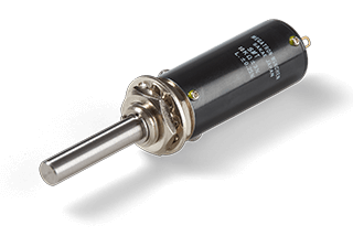
A multi-turn potentiometer has a shaft that can rotate several times, using a mechanism to move the wiper along a long resistive path. This design allows small changes in the angle to be spread over more resistance, providing finer control and smoother adjustments for precise movements. It is important for all the parts to fit together properly, as bearings, bushings, and special gears keep the wiper aligned, ensuring that the signal stays consistent throughout the full range of motion.
Good scaling is crucial because it matches the working turns to the controller’s input range. This helps avoid any clipping of the signal. Additionally, having a simple acceptance process, including checking the baseline, verifying the center point, running step tests, and assessing low-speed noise, helps confirm that everything functions correctly in a quick and repeatable way.
Multi-Turn Potentiometer Accuracy: Scale, Backlash, Resolution
Multi-turn accuracy relies on how we convert motion. Helical tracks help create smooth movement, while gear trains can stretch angles, which introduces some resistance. Choosing the right gears is essential because it can affect backlash. It’s best to measure and account for this early on.
Keep the wiper current low by using the formula Iw = Vs / Rtotal. Ensure Rtotal matches the ADC input for stable and accurate readings. When setting up the controller, determine how many counts you want per turn and confirm that the smallest command moves at a slow speed.
For verification, establish a home index and log counts every quarter-turn throughout the usable range. When you reverse, do it gently at the same points to observe any effects from gear lash. It’s also helpful to warm the unit for ten minutes before checking offsets again, as this helps catch any thermal drift. This ensures everything runs smoothly and reliably. If you need a single-turn refresher for comparison, see Rotary Potentiometer Working Principle.
Multi-Turn Potentiometer Reliability: IP Sealing, Temperature, Vibration
End of travel protection preserves scale and hardware life. Use positive stops or a clutch to prevent wiper damage at the extremes. Pick a lubricant for the real temperature range so that the feel and backlash stay steady. Seal the bushing with an O-ring and fit rated cable glands with strain relief. In humid sites, add a hydrophobic breather and route a drip loop. Prove the barrier with a short spray test, then run an angle check.
Heat and vibration can shift readings when alignment moves. Run hot and cold soaks and a vibration sweep near local machinery speeds. Compare traces before and after to track drift per turn and center offset. Use bearings that hold alignment and anti-backlash features for frequent reversals. For long linear strokes that need similar precision, see Precision Linear Motion Potentiometers.
Multi-Turn Potentiometer Applications: Valves, Joysticks, Test Stages
Dosing Pumps and Blend Mixers
Multi-turn panels let operators set fine flow rates without overshoot. Map usable turns to the controller span, lock the dial after setup, and log a short step response at typical setpoints. For closed-loop valve control in process lines, explore ETI System: Control Valve Actuators and Positioners.
- Map turns to span; avoid hard stops in routine use
- Add a dial lock or detent to hold setpoints
- Log 2–3 setpoints per shift for quick recovery
- Recheck after CIP washdown with a brief spray test
Precision Optics and Test Stages
Fine stages benefit from smooth, predictable trim. Choose conductive plastic for low noise at crawl speed, shield analog runs, and mark a home index for re-zero. For non-contact cabin controls that set coarse targets, see Understanding Hall Effect Joysticks For Mobile Equipment.
- Pick Rtotal for your ADC; keep Iw low
- Use twisted pairs and single-point ground
- Save a baseline sweep and mid-span anchors
- Note hysteresis across small reversals
Coarse and Fine Control with Joysticks
Set a coarse target with a joystick, then finish with a multi-turn knob for precision. Keep cable runs short, land shields at one end, and confirm home and span after warmup. For the sensing inside non-contact sticks, see How do Hall Effect Joysticks Work?
- Verify monotonic steps per turn at crawl speed
- Check center drift after 10-minute soak
- Store the home index and span in the controller
- Keep a quick step script for field checks
Specifying Multi-Turn Controls: Turns, Resistance, Fit, Checks
Develop a specification suitable for the plant environment. Align motion, scaling, and site conditions with a unit that fits your hardware, covers the input range, and maintains calibration.
Set Turns, Index, and Dial
Define total and usable turns, choose a dial or turns counter, and record a home index for fast re-zero. Map usable turns to the controller span so you do not clip at either end.
Choose Element, Ohms, and Taper
Pick conductive plastic, wirewound, or cermet for duty and temperature. Size total resistance for ADC input impedance and noise limits; keep Iw small. Select a linear or custom taper to match how the mechanism moves.
Align Shaft, Bearings, and Backlash
Match shaft size, bushing thread, and panel thickness. Choose bearings or bushings for load and life, and note rotational torque. Use anti-backlash gears where frequent reversals are expected.
Seal, Wire, and Verify
Match IP level and materials to site chemistry. Use twisted pairs, land shields at one end, and add strain relief. Save a baseline sweep, a few setpoints per turn, and a step response so service has quick pass or fail checks.
Why Choose ETI Systems
ETI Systems builds sensing and control hardware for real plants. We make rotary and linear potentiometers, industrial joysticks, and valve actuators. We are ISO 9001:2015 certified. Engineering sits beside production. That speeds prototypes and keeps feedback tight. We tune element type, resistance, taper, and mechanics to your I/O. Every unit is verified for scale and linearity. We check the center, noise, and monotonic steps. Parts ship with clear mounting and I/O notes.
We help teams commission faster and service with confidence. Ask for an acceptance pack with baseline sweep and approach repeatability. It includes step response, low-speed noise, and recorded scaling. You also get 2D and 3D CAD. We provide wiring and grounding guidance. Sealed and redundant builds are available when sites demand more. Need a configured option? Our applications engineers review the duty and environment. Then they recommend the right ETI model. Integration stays clean from drawing to line.
Frequently Asked Questions
Choose turns based on needed resolution and travel. Use 5 for coarse, 10 for fine, 20 for very small; map usable turns to the controller span.
Creep forward and back to the same mark and log the delta. If it exceeds your band, add anti-backlash gears or a small software deadband and recheck warm.
Size total resistance to the ADC input and cable length. 5–10 kΩ suits short runs; keep Iw = Vs/Rtotal low to cut noise and wear.
Use positive stops or an internal clutch. Set soft limits in software, store a home index, and recheck span after service.
Sweep slowly through usable turns and log the same points each turn. Compare the error to the spec and save the trace as your baseline for audits.
Ready to specify? Share your range, environment, and I/O. We will match an ETI Systems model that installs cleanly, scales correctly, and holds calibration.