Small shifts in position feedback can stall a line, blur batch records, and send operators back to retuning. The causes hide in ordinary choices, from the electrical range you select to the way the sensor is mounted and wired. If you want loops that settle quickly and stay there, begin by understanding what truly drives a clean signal on the plant floor. ETI Systems designs and manufactures rotary and linear potentiometers that provide clear and repeatable signals in production equipment. In the following sections, we will explain how to match motion to the electrical range and ensure proper installation for stable readings. We will also highlight the models that are best suited for your needs.
Control quality rises and falls with the feedback your controller sees. Below, we explain how Potentiometers convert motion into a clean, proportional signal that keeps loops calm and setpoints on target.
A potentiometer translates shaft rotation or linear travel into a proportional voltage. The controller reads this change to know where the mechanism sits at any moment. Clean conversion allows tighter setpoints and faster recovery after disturbances.
In closed-loop systems, stable feedback reduces hunting and overshoot. Simple calibration aligns the sensor output to the mechanical zero and span. When calibration holds, operators spend less time retuning and more time running the product.
Your mechanism’s motion and duty cycle set the rules for sensor construction. Use the notes below to choose the Potentiometers that hold calibration and deliver the service life you expect.
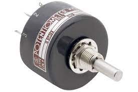
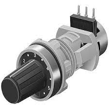
Best for compact mechanisms with limited angles. Select electrical angle, shaft style, torque profile, and resistance value that match space and signal needs. Conductive plastic elements support smooth response and long service life.
Used where straight-line travel is easier to sense. Choose stroke length, mounting, and guidance that protect alignment. Proper support prevents side load on the shaft so readings remain accurate across the full stroke.
Element choice affects wear, linearity, and noise. Conductive plastic offers smooth output and a strong life for continuous duty. Match the material and expected cycles to the application so performance stays consistent.
Accuracy comes down to a small set of specs you can measure and verify. Use the notes below to set targets that keep readings steady and repeatable.
Linearity describes how closely the output matches the ideal across the range. Resolution describes the smallest change the system can detect. Tighter linearity and adequate resolution reduce trim time and improve repeatability.
Electrical angle or useful stroke defines the portion of travel that produces a valid signal. Align this range with the mechanical motion and add a safety margin at each end. Good alignment prevents clipping and preserves full control authority.
Select a resistance value and tolerance to match the input stage of the controller. Lower noise and stable contact yield steady readings. Verify output with the intended supply and input so the whole chain works together.
How the device mounts and moves affects signal quality as much as the datasheet. Use the practices below to protect accuracy.
Solid mounting keeps geometry consistent. Use couplings that respect misalignment limits and avoid side load. Check runout and parallelism so the element sees smooth motion rather than binding.
Appropriate bearing support and light shaft loads protect the element and wiper. Minimize backlash in the drive so small moves appear cleanly at the output. These basics extend life and keep calibration stable.
Select sealing and IP protection that match site conditions. Moisture, dust, and cleaning fluids can degrade contacts and elements. Proper gaskets, strain relief, and connector choices keep the signal stable between services.
Even a good sensor needs a clean path to the controller. The steps below help you preserve the quality of the measurement.
Use twisted pairs and shielding on long or noisy runs. Terminate the shield at one end at the control panel ground to avoid ground loops. Route sensor cables away from drives, contactors, and VFD output leads, and keep them separate from power. Verify continuity and insulation resistance before the system goes live.
Quick value checks
Match the potentiometer supply and the controller reference so readings are ratiometric and stable. Choose a low-pass cutoff that smooths noise without slowing control; start near one-fifth of the fastest expected position change and fine-tune during commissioning. Confirm ADC range, resolution, and sampling so that full travel uses most of the counts.
Quick value checks
Record zero and full scale after installation and save the plot. Add a short verification to routine rounds and after any mechanical work. Track temperature with readings to spot drift and set simple alert bands that prompt a quick recalibration rather than a full retune.
Quick value checks
ETI Systems builds feedback components for industrial work. Our portfolio covers rotary and linear Potentiometers with options that fit tight spaces, long strokes, and rigorous duty cycles.
Compact rotary models support a range of electrical angles and shaft styles. Conductive plastic elements deliver smooth response and dependable life. Options for bushings and bearings help match mounting and load conditions.
Linear series provide a clear position over fixed strokes. Choices in body length, mounting, and rod ends simplify integration. Stable guidance protects alignment and preserves accuracy across the travel.
Application needs vary across machines and industries. We help teams choose values, angles, strokes, and terminations that fit their drawings and service plans. Clear documents and responsive support speed design and approval.
Start by mapping motion and duty to an electrical range that your controller can use. Follow the steps below to turn that into the correct part number.
Document the total angle or stroke and the true operating range. Confirm available space, coupling style, and alignment allowances. Add an end margin so the useful range stays within the sensor limits.
Select element type, resistance value, tolerance, and linearity target. Align the electrical angle or useful stroke with motion. Verify the expected life against duty cycles in the application.
List temperature range, moisture, dust, and cleaning exposure. Choose sealing, connectors, and strain relief to suit the site. Add simple visual checks and periodic calibration to the maintenance plan.
Confirm supply, input range, filtering, and grounding with the actual controller. Save datasheets and baseline plots for future checks. This documentation shortens audits and service work.
ETI Systems is dedicated to designing and manufacturing precision control components for industrial automation. Our extensive product line includes industrial joysticks, rotary and linear potentiometers, and electric valve actuators for fluid control. We focus on ensuring steady motion and reliable feedback by rigorously validating materials, seals, and temperature performance, which helps maintain stable signals and movements throughout service intervals.
When your operations require accurate sensing and motion, we provide tailored solutions to align the sensor and actuator with your specific needs. For potentiometers, we guarantee that the electrical angle, resistance, and lifespan are perfectly suited to the mechanism and its intended use. For actuators, we accurately size torque or thrust, travel distance, and control signals based on your valve and environmental conditions. We offer options for both on/off and proportional control, along with feedback mechanisms that fit seamlessly into your calibration routines.