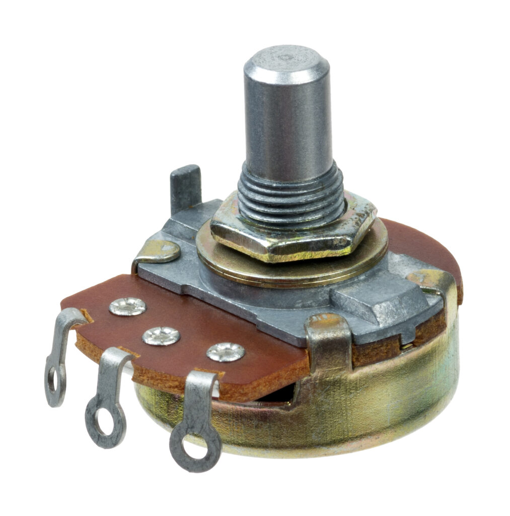
A rotary potentiometer converts the angle of a shaft into a proportional voltage by moving a wiper across a resistive track. The output changes with the supply voltage. This helps the controller maintain a steady scale, even when the supply changes. Potentiometers are easy to repair and check, making them a reliable option for industrial feedback.
The effective operation of a potentiometer relies on three key factors: mechanical fit, clean contact, and accurate scaling. Proper alignment of the shaft and bushing ensures a correct fit. Whereas adequate contact force stabilizes the signal at low speeds. Additionally, appropriate resistance and taper should match the input impedance for optimal performance. With a brief acceptance routine that includes a baseline sweep, center and span checks, and a few saved points, commissioning can be completed quickly and consistently.
Rotary Potentiometer Accuracy: Track, Wiper, Contact
A contact sensor performs optimally when it provides precise readings and detects minor movements. Choosing the appropriate type for your requirements is essential. Conductive plastic is ideal for quiet operation and smooth functionality. For heat resistance and heavy-weight support, choose wirewound sensors. For applications that need tight linearity and thermal stability, cermet is the best option.
Make sure to set the total resistance for your Analog-to-Digital Converter (ADC) and account for cable length. This helps keep the wiper current low and minimizes noise.
Validation should be simple and repeatable. Map the usable electrical angle to the mechanical limits so that you avoid dead zones at each end. Take readings at the center, mid-span, and near the ends using a slow sweep. Always read ratiometrically, connect ground returns at a single point, and use twisted pairs for the signal. Following these guidelines will help ensure consistent results and reduce the need for extensive tuning.
The choice of elements and wiper design affects resolution and noise. Conductive plastic is good for fine adjustments at low speeds. On the other hand, wirewound options can handle heat and higher currents better. It’s important to choose a wiper that balances force and wear. After selecting the wiper, check for noise during slow movements and direction changes. Smooth traces without chattering indicate stable contact.
How you mount the components is also important. Ensure the shaft is straight with the right bushings or bearings. Check the end stop angle and index, and pay attention to the torque applied during rotation. A quick test can help you monitor noise and linearity over a few hundred cycles. This will help confirm your choice before the part goes into production.
Potentiometer Sealing & EMC Practices for Plant Floors
Plants often face challenges like washdown, dust, and vibration. It’s important to match the IP rating to the cleaning pressure. Using sealed shafts and O-rings can help protect your equipment. Also, be sure to use cable glands with strain relief that offer some flexibility instead of just relying on loading pins.
If condensation is possible, use a hydrophobic breather. Create a drip loop to stop fluid wicking. After sanitation, do a quick spray test. Check angles again to confirm proper alignment.
Temperature and shock can affect how equipment feels and performs. To ensure stability, you should conduct hot and cold soaks along with a vibration sweep, especially close to local machinery frequencies. Using bearings or bushings is essential for maintaining alignment at speed, while locking hardware helps keep the preload secure. It’s beneficial to record any drift before and after tests.
For long-stroke feedback on linear axes, consider using precision linear motion potentiometers. Choose materials for elastomers and housings that can handle your site’s chemicals, like FKM, EPDM, or PTFE seals. Also, use anodized or stainless steel for corrosion resistance. Keep your cable runs short, separate power cables from analog ones. Ensure to use twisted pairs, and connect shields at one end to avoid issues.
Connector choices affect uptime. Use sealed, keyed plugs with proper plating, seat gaskets square, and follow the manufacturer’s torque. Label leads clearly and keep a small service loop for strain relief. These small details prevent intermittent faults that look like sensor drift.
Potentiometer Applications: Skids, Mobile Equipment, Pick-and-Place
Utilize these snapshots to select components, plan quick inspections, and steer clear of common failure points.
Valve Position Feedback on Skids
Conductive plastic tracks yield smooth, low noise feedback, so valves trim predictably through media changes. Read ratiometrically, protect entries from washdown, and confirm span after service. For a broader control view in process plants, explore ETI System: Control Valve Actuators and Positioners.
- Map the electrical angle to valve travel and avoid end stops in normal operation
- Seal shafts and glands; run a short spray test post maintenance
- Log stroke time and a small step response across the band
- Save LRV/URV scaling and a baseline trace for quick recovery
Joystick Feedback in Equipment Control
Wirewound elements tolerate heat, shock, and sustained load while giving a clear center and crisp ends. Grounding and ratiometric reads keep signals steady near engines and pumps. If you are comparing contact and non-contact control inputs, see How do Hall Effect Joysticks Work? for a useful contrast.
- Choose resistance to fit ADC input and cable run
- Verify center deadband and hysteresis with a slow sweep
- Use sealed connectors and strain relief to protect leads
- Keep a replacement kit with alignment marks and a short step script
Linear Axes in Pick and Place
Low noise linear elements support repeatable placement at speed. Align mounts to avoid side load, shield properly, and confirm teach points at shift change. For multi-revolution angle sensing, How does a Multi Turn Potentiometer Work provides helpful background on extended range reads.
- Specify stroke with margin; align to avoid side load
- Use twisted pairs and single-point ground; check noise at the crawl
- Record stroke time and setpoints as a baseline
- Trigger maintenance when the drift exceeds your allowed band
Guide to Select Rotary Potentiometer: Electrical Angle, Taper, Interface
Develop a specification that functions effectively in the plant. Align motion, scaling, and site conditions with a unit that suits your hardware, covers the input range, and maintains calibration.
Map Angle to Input Scale
Set the total travel and how the shaft moves across the element. Map the usable electrical angle to mechanical limits so the reading matches the design. Confirm end stop position and reference index against the drawing.
Choose Element Type and Total Resistance
Select conductive plastic, wirewound, or cermet based on duty, noise level, and temperature. Size total resistance and taper to your circuit and scale. Verify linearity over the working band and resolution at small steps; consider dual gang options for redundancy or offset channels.
Set Shaft, Bearings, and Torque
Fit shaft diameter and length, bushing thread, and panel thickness to your hardware. Choose bearings or bushings that match life and load. Confirm rotational torque and alignment so the wiper lands where the drawing expects.
Seal, Wire, and Prove Performance
Match IP rating and seals to washdown and dust. Use strain relief and routing that avoids wiper lead stress. Save a baseline sweep and a few setpoint readings for later comparison. For cabin layouts and off-road controls, Understanding Hall Effect Joysticks For Mobile Equipment offers practical context.
ETI Systems: ISO 9001 Potentiometers, Joysticks, and Actuators
ETI Systems makes high-quality rotary and linear potentiometers and joysticks. We follow ISO 9001:2015 standards for production. Our engineering and production work closely together. We customize specifications like resistance and taper for your needs. Each component is vital for your system’s performance. Every unit is tested for scale and accuracy. This ensures reliable performance from the start. You can trust our products for daily use..
In addition to our commitment to high performance, we prioritize a seamless user experience through fast commissioning and straightforward service protocols. On request, we provide an acceptance pack that includes a baseline sweep, approach direction repeatability, step response at key setpoints, low-speed noise analysis, and recorded scaling. This in-depth documentation not only aids in your implementation but also serves as a valuable reference for future maintenance.
Furthermore, we understand that integration can be complex, which is why we offer 2D and 3D CAD files, comprehensive wiring and grounding guidance, and a variety of material options, including sealed and redundant builds designed for washdown environments or safety-critical applications. Our applications team is always on hand to analyze specific duties, environmental factors, and I/O requirements, ensuring that we guide you to the ideal ETI model for your needs, complete with a clear and effective integration path..
Frequently Asked Questions
Shaft angle. The wiper moves across a resistive track and outputs a voltage that is proportional to rotation when read ratiometrically.
Pick a value that suits the input impedance and cable length so wiper current stays low and noise remains stable.
Run a slow sweep and log readings at the center, mid span, and near the ends. Keep that trace as your baseline and repeat it after service.
Match IP rating to cleaning pressure, use sealed shafts and rated glands, and route a drip loop. Confirm with a short spray test and angle check.
When the motion is translational. See Precision Linear Motion Potentiometers for stroke feedback on guided axes.
Ready to specify? Share your range, environment, and I/O. We will match an ETI Systems model that installs cleanly, scales correctly, and holds calibration.