Small gaps between command and motion can lead to significant inefficiencies on the floor. A Hall Effect Joystick helps bridge this gap by converting intent into a stable signal that maintains position, repeats accurately, and resists the noise that can disrupt control loops. The result is smoother movements, reduced alarm triggers, and operators able to focus on production rather than constantly readjusting settings.
However, the joystick is only part of the solution. Many machines also use linear motion sensing for precise adjustments and verification. In the following sections, we will explain how Hall sensing operates at the joystick, how linear potentiometers enhance feedback throughout the travel range, and how ETI Systems integrates these technologies so that your controller accurately reflects the mechanism’s performance.
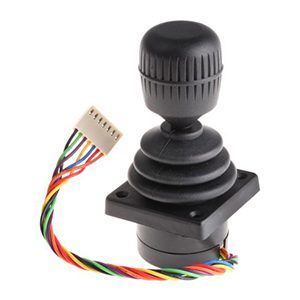
Good automation starts with signals the controller can trust. Below, we show how a Hall Effect Joystick produces that trust in daily operation.
Two lines of magnets and sensors convert stick movement into a proportional voltage without physical contact. No wiping means minimal wear and a signal that stays stable across long duty. That stability shows up as repeatable starts, predictable stops, and less drift over time.
Operator takeaways
Hall devices produce ratiometric outputs that track supply changes and resist electrical noise when wired well. Clean routing, shielding, and grounding protect the signal near drives and contactors. The payoff is fewer nuisance alarms and tighter control bands.
Operator takeaways
Comfortable grips, defined detents, and consistent return‑to‑center reduce fatigue and improve repeatability. Integrated switches and interlocks simplify safe behavior at the panel. The right layout helps operators move fast without losing accuracy.
Operator takeaways
Some tasks need continuous feedback along a straight path. Here is how rotary control at the stick pairs with linear sensing for fine‑tuned motion.
Useful stroke should exceed mechanical travel by a small margin so calibration lands cleanly within range. Tight linearity and adequate resolution shorten trim time and keep repeatability high. The combination lets the controller read small changes without jitter.
Setup checklist
Accurate readings depend on clean mechanics. Solid mounts, guided rods, and proper coupling prevent side load on the element. Good alignment keeps the signal smooth across the whole stroke and extends service life.
Setup checklist
Even a good sensor needs a clean path. Twisted pairs and shields limit pickup, filtering removes noise without slowing control, and calibrated zero and span keep the scale honest. Short checks during rounds catch drift early.
Setup checklist
ETI Systems builds control components for industrial work. Our Hall Effect Joystick families and linear motion potentiometers are engineered for smooth response, trustworthy feedback, and long service life in demanding environments.
Rugged bases and guided mechanics pair with non‑contact Hall elements for repeatable signals. Options include single or multi‑axis control, centering behavior, and integrated switches. Clear wiring and setup notes speed commissioning and support.
Design highlights
Linear units cover common strokes with conductive‑plastic elements for smooth output. Choices in mounting, body length, and terminations simplify integration. Stable guidance protects alignment so readings stay accurate between services.
Design highlights
Selection processes become more efficient with clear diagrams and proper signal guidance. We assist teams in aligning electrical angles, resistance, and output with the controller, while also mapping mounting and coupling to actual hardware. Our goal is to create a clean signal chain that connects the stick and sensor to the PLC.
Design highlights
Begin with motion and environment, then choose outputs and options that match your controls and operators.
Confirm the number of axes and the expected travel on each. Choose centering behavior and detents that fit the job and the operator’s needs. Match grip and switch placement to frequent actions to reduce errors.
Spec checklist
Pick analog ranges, switched signals, or digital outputs that align with available I O. Plan diagnostics for out‑of‑range values and loss of signal. Record a baseline at commissioning for future checks.
Spec checklist
Match sealing, materials, and temperature range to the site. Verify expected duty and cycles with your maintenance plan. The right protection keeps the signal stable through cleaning, heat, and vibration.
Spec checklist
ETI Systems specializes in the design and production of high-precision control components for industrial automation. Our offerings include advanced joysticks, rotary and linear potentiometers, and electric valve actuators. Our Hall Effect Joystick designs combine non-contact sensing with guided mechanics to deliver smooth proportional output, consistent return to center, and low drift across long duty. Materials, sealing, and temperature performance are validated so signals stay steady near drives, during washdown, and under vibration.
When you specify a Hall Effect Joystick with ETI Systems, we help you match axes, travel, centering, outputs, and diagnostics to your controller and environment. Options include single or multi-axis control, detents and integrated switches, and clear wiring that speeds commissioning. Drawings, baseline calibration guidelines, and application support keep loops stable after startup, while authorized distribution and traceable parts simplify purchasing.