Every automated production line experiences its share of bottlenecks. These can occur due to issues such as a valve that overshoots, a control loop that oscillates, or a batch process that deviates slightly, which results in wasted hours. The actuator turns a command into motion with little noise or heat. When it performs correctly, bottlenecks ease, setpoints stay steady, Clean-In-Place (CIP) cycles finish sooner, and operators make fewer adjustments.
Use this guide to choose and size an electric valve actuator for fluid control. It also shows where ETI Systems’ solutions fit, so you can move from specs to reliable motion.
Efficiency in automation means the valve moves to the commanded position and stays there with little human touch. The controller trusts the position it reads because the feedback is steady and the response is smooth. Tight positioning, low hysteresis, and predictable behavior keep loops calm and setpoints on target.
In plants, heat, moisture, and vibration try to pull that performance off course. A capable actuator holds calibration, seals out the elements, and keeps bearings and gears running clean for years. It also withstands start-and-stop cycles, continuous modulation, and high duty demands without drifting from its setpoint. This stability is what gives engineers confidence that loops will remain steady and processes will be predictable.
Integration should be just as dependable. Match standard signals with your PLC or DCS, verify end limits and feedback during commissioning, and record a baseline response for quick future checks. Add brief functional tests to routine rounds, confirm torque or thrust margins after any valve change, and maintain a small spares kit for critical loops. With simple inspections, periodic calibration, and a clear service plan, teams can standardize across skids and lines, protect uptime, and schedule maintenance windows on their terms.
Choosing an actuator requires understanding how the device interacts with real operating conditions and what performance means for your process. Each factor below influences efficiency, safety, and long-term reliability, so every decision should be made with those outcomes in mind.
Start by sizing the work the valve presents: the force or torque required, the stroke or angle to travel, and the time allowed to make that move. Valve size, media properties, and line pressure all shape these numbers. Getting them right keeps the Actuator moving smoothly and prevents unnecessary load on the motor and gearing.
Small positional errors, in many applications, can result in wasted products or out-of-specification products. An actuator capable of precise resolution and low backlash is the stabilizing presence that control loops rely on. Accurate feedback devices (potentiometers, Hall sensors, encoders) keep the controller and operator aligned with the true valve position.
Integration with plant controls is central to achieving the performance. Select whether the application needs a simple on/off action, proportional analog response, or advanced digital communication. Matching the actuator’s interface with the control system reduces commissioning time and supports straightforward troubleshooting throughout its service life.
Every site introduces its own challenges. Moisture, dust, vibration, or chemical exposure can degrade performance if the actuator is not designed for those conditions. Choosing the right ingress protection level, construction materials, and protective coatings ensures that the actuator maintains accuracy and reliability under stress.
Applications that involve frequent modulation or extended operation generate heat within the actuator. A design rated for the correct duty cycle and equipped with appropriate thermal capacity will continue to perform without drift or shutdown. This prevents unexpected failures and extends the life of internal components.
Beyond normal operation, actuators must perform correctly in abnormal conditions. Verifying voltage compatibility, power draw, and start-up inrush is only the beginning. Engineers must also specify what the actuator should do in a power loss: move to a safe position, remain in place, or complete a programmed sequence. Integrating clear limits and safety interlocks ensures confidence in critical scenarios.
The upfront purchase is only part of the investment. Long-term value comes from actuators that require minimal service, offer easy access for calibration, and use components that can be replaced quickly. Evaluating lifecycle cost encourages choices that lower total ownership expense and support reliable plant operation year after year.
Electric valve actuators turn control intent into steady motion that protects product quality and energy use. They hold position with fine resolution, respond smoothly to small command changes, and connect cleanly to common PLC architectures. The outcome is tighter loops, fewer nuisance alarms, and quicker commissioning on new lines and retrofits.
They also lower the ongoing service effort. With no compressors to maintain and fewer exposed moving parts, electric designs keep calibration longer and make routine checks simpler. Across water and wastewater, HVAC, chemical dosing, food and beverage, and OEM skids, electric actuators deliver accuracy with low upkeep and a clear path to lower total cost of ownership.
· Required torque/thrust and total travel
o Calculate breakaway, running, and seating torque or thrust with process pressure and media effects.
o Define the full stroke or angle and the opening/closing time your loop expects.
o Add margin for sticky seals, viscosity changes, and seasonal conditions so the Actuator does not stall.
· Resolution, hysteresis, and feedback type
o Specify command resolution and allowable deadband for the control loop’s stability needs.
o Measure mechanical backlash and verify repeatability across temperature and load.
o Choose a potentiometer, Hall sensor, or encoder feedback based on calibration discipline and accuracy targets.
· On/off or proportional control (and signal levels)
o Match interface to your PLC or DCS: discrete, analog (e.g., 4–20 mA), or digital protocol.
o Confirm scaling, filtering, and update rates so commands and readings remain steady.
o Define diagnostics for loss of signal, feedback mismatch, and travel faults.
· Duty cycle and thermal constraints
o Map the expected cycle profile to the actuator’s duty rating and thermal capacity.
o Check stall behavior, cooldown characteristics, and ambient temperature limits.
o Review enclosure space and mounting orientation so heat can dissipate.
· IP rating, temperature, and vibration tolerance
o Select ingress protection that matches washdown, dust, or outdoor exposure.
o Confirm operating and storage temperature ranges with real site conditions.
o Assess vibration levels and specify fasteners, connectors, and strain relief accordingly.
· Power supply and fail position
o Verify voltage, frequency, inrush current, and protective device sizing.
o Define fail open, fail closed, or last position based on process risk and recovery plan.
o Set travel and torque limits and interlocks for safe behavior during faults and start-ups.
· Service intervals and expected life
o Plan routine checks for limits, feedback calibration, seals, and connectors.
o Stock common spares and record a baseline response for quick comparisons.
o Use lifecycle data to schedule maintenance windows and reduce unplanned downtime.
Assess ease of calibration, access for inspection, and the average life of bearings, seals, and gearing. Choose models with predictable maintenance schedules to lower lifecycle cost.
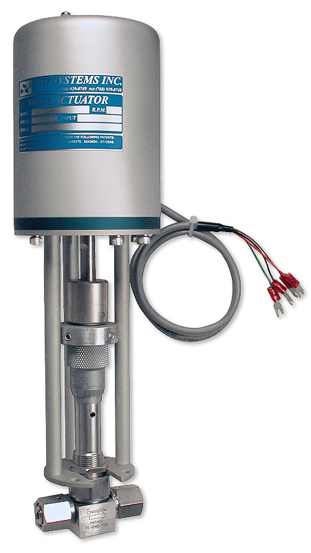
ETI Systems designs and manufactures precision control components for industrial automation. Our portfolio includes industrial joysticks, single-turn and linear motion potentiometers, and electric valve Actuator solutions for fluid control. We focus on accurate positioning, smooth response, and long service life so OEMs and plant teams can trust the readings their controllers see and the motion their valves deliver.
For fluid systems, our electric valve Actuator lineup is built for reliable, repeatable control. Options include on/off and proportional control, robust feedback devices, and mechanical configurations for rotary and linear valves. Sealing and materials are chosen for tough sites, while clear wiring and setup steps shorten commissioning. When you need stable loops, clean PLC integration, and low routine service, ETI Systems is ready to match the Actuator to your torque, signal, and environment.